Printed circuit board material requirements

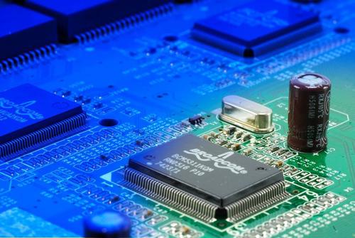
In today's wireless communication equipment, the radio frequency part often uses a miniaturized outdoor unit structure, while the outdoor unit's radio frequency part, intermediate frequency part, and low frequency circuit part that monitors the outdoor unit are often deployed on the same PCB circuit board material. Therefore, in terms of how to prevent the interference between radio frequency, intermediate frequency and low frequency circuits, there are high requirements for PCB materials.
Hybrid PCB design is a big problem, and it is difficult to have a perfect solution. In general, RF circuits are placed and routed as an independent board in the system, and even have a special shielding cavity. And the RF circuit is generally single-sided or double-sided, the circuit is relatively simple, all of these are to reduce the impact on the distribution parameters of the RF circuit and improve the consistency of the RF system. Compared with the general FR4 material, the RF circuit board tends to use a high-Q substrate. This material has a relatively small dielectric constant, a small distributed capacitance of the transmission line, high impedance, and a small signal transmission delay.
In the design of mixed circuit boards, although radio frequency and digital circuits are made on the same PCB, they are generally divided into radio frequency circuit areas and digital circuit areas, which are laid out and routed separately. Use a ground via and a shield box to shield.
In high-speed, high-density PCB design, crosstalk (crosstalk interference) really needs special attention, because it has a great impact on timing (timing) and signal integrity (signal integrity). Here are some points to note: Choose the appropriate termination method. Continuity and matching of trace characteristic impedance control.
The size of the circuit board trace spacing. The distance often seen is twice the line width. You can use simulation to know the effect of trace spacing on timing and signal integrity, and find the minimum tolerable spacing. The results of different chip signals may be different.
The materials for printed circuit board are generally FR-4, high frequency material (CCL), Rogers, High TG FR4, Middle TG FR4, Normal TG FR4, Halogen Free and other laminates.
Copyright © 2025 A-TECH CIRCUITS Co., Ltd. | All Rights Reserved
Hello, please leave your name and email here before chat online so that we won't miss your message and contact you smoothly.