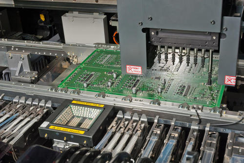
Making a PCB board is not a simple process to complete the board, just drill a hole and put the components on it. PCB fabrication is not difficult, the difficulty lies in the troubleshooting after the completion of the production. Whether it is an individual enthusiast or an industry engineer, it is quite a headache for the PCB board to encounter problems during debugging, just like a programmer encounters a BUG.
Common PCB circuit board faults are mainly concentrated on components, such as capacitors, resistors, inductors, diodes, transistors, field effect transistors, etc., the integrated chip and the crystal oscillator are obviously damaged, and the method for judging the fault of these components can be passed. Eyes to observe. The surface of electronic components with obvious damage has obvious burning marks. Such a failure can be solved by directly replacing the problem component with a new one.
Of course, not all electronic components can be visually observed, such as resistors, capacitors, and triodes. In some cases, damage cannot be seen from the surface and requires professional inspection tools. Commonly used inspections include: multimeters, capacitor meters, etc., when it is detected that the voltage or current of an electronic component is not within the normal range, indicating that there is a problem with the component or the previous component, and directly replace it and check to see if it is normal.
General inquiries & Customer Service
Tel: 86-755-2335 9039 | Fax: 86-755-3318 0939
E-Mail: Enquiry@atechcircuit.com
Skype: atechcircuits

Headquarters: 602, Building B3, Zhimei Huizhi Industrial Park, Fuyong Street, Bao'an District, Shenzhen City, China
Copyright © 2025 A-TECH CIRCUITS Co., Ltd. | All Rights Reserved
Hello, please leave your name and email here before chat online so that we won't miss your message and contact you smoothly.