Latest products
Explanation of the layout process of SMD components in PCB
by:A-TECH
2021-03-30
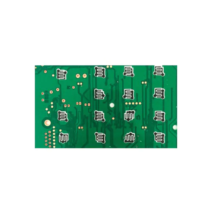
Based on the design guidance documents of a large company in Taiwan, this article combines some of my own experience and understanding, and discusses some production process requirements in the PCB layout. Pay attention to these requirements in the PCB layout to avoid a lot of unnecessary troubles. 1. SMD component LAYOUT minimum spacing. Ensuring a certain component spacing during SMDLAYOUT can reduce the probability of virtual soldering, bridging, shadow effects and other problems during soldering. Figure 1. Horizontal spacing of components Figure 2. Vertical spacing of components 2. SMDPCB should not be LAYOUTSMD components within 3mm from the sides of both panels. This is mainly because the guide groove of the placement machine requires that no components are allowed within 3 to 5 mm of the PCB board edge. 3mm is the minimum requirement. If this size is really not guaranteed, you can consider using V-shaped grooves or stamp holes to lengthen the board, and then skim off the excess board after welding. Figure 3. SMDPCB board edge requirements 3. SMD arrangement direction. (a) The same components should be arranged in the same direction as possible. (b) On the same golden road, a test point must be left with a diameter of 30 mils. 4. When SMD and PTH devices are mixed and formed by wave soldering at one time, (a) The arrangement direction of CHIP, SOT, SOIC components should be as perpendicular as possible to the over-tin direction to avoid shadow effects. (b) Components whose body heights are too different should not be arranged close to avoid shadow effects. (c) It is best for any component to be arranged in parallel and perpendicular to the tin-through direction. The shadow effect is the PCB layout that must be considered when using wave soldering to solder SMD components. If reflow soldering is used, there is no such problem. The so-called shadow effect, for example, when there are two SMD components with very different component heights close together, if the tall component passes the tin first, it may be possible that the resistance of the high-body component causes the lower tin to pass. Body components cannot eat tin, which is the shadow effect of high body components. Figure 4. When wave soldering is used, the component arrangement (d) must be arranged at right angles (vertical), and sufficient tin space must be reserved. The space distance should be 0.635mm. Figure 55. SMTLAYOUT causes solder dead angle (empty soldering) The following figure shows the situation that may cause empty soldering. In the specific layout, you need to consider whether the layout may cause empty welding during welding. All in all, it needs to be used flexibly and cannot be mechanically applied. 6. V-CUT reference data (1) FR-2, CME-1, OAK910 (semi-glass fiber) PCB thickness 1.6mm The depth of the V-CUT cutter is 0.4mm×2 sides. FR-4PCB thickness is 1.6mm, V-CUT cutter depth is 0.5mm×2 sides.
Custom message