Analysis of the realization process of PCB copy board technology
by:A-TECH
2021-03-14
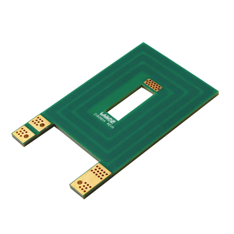
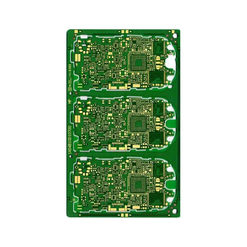
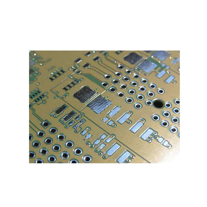
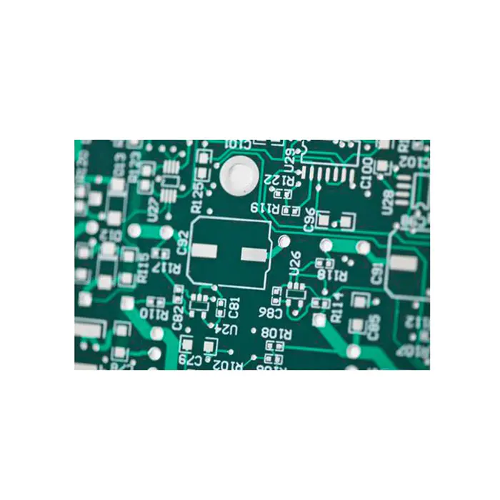
As we all know, first scan the circuit board to be copied, record the detailed location of the components, and then disassemble the components to make a bill of materials (BOM) and arrange the material purchase, and the blank board is scanned into a picture and restored by the copy board software. PCB board drawing file, and then send the PCB file to the plate making factory to make the board. After the board is made, the purchased components are soldered to the made PCB board, and then the process of testing and debugging the circuit board is called PCB copy board. Technology. The technical realization process of PCB copy board is mainly completed through the following seven steps. In the first step, when we get a PCB, we should first record the model, parameters, and positions of all vital parts on paper, especially the direction of the diode, the tertiary tube, and the direction of the IC gap. If possible, it is best to use a digital camera to take two photos of the location of vital parts. The second step is to remove all the components and remove the tin in the PAD hole. Clean the PCB again. You can clean it with alcohol. After cleaning, put it in the scanner. Then lightly sand the top and bottom layers with water gauze paper until the copper film is shiny. Put it in the scanner, start PHOTOSHOP, and use the color method. Sweep in the two layers separately. The third step is to adjust the contrast and brightness of the canvas to make the part with copper film and the part without copper film have a strong contrast, then turn the second image into black and white, and check whether the lines are clear. If not, repeat this step. If it is clear, save the picture as black and white BMP format files TOP BMP and BOT BMP. If you find that the graph has #alink 10806#, you can also use PHOTOSHOP to repair and correct it. The fourth step is to convert the two BMP format files to PROTEL format files, and transfer two layers in PROTEL. For example, the positions of PAD and VIA that have passed through the two layers basically coincide, indicating that the previous steps are well done. If If there is a deviation, repeat the third step. Therefore, PCB copying is a task that requires patience, because a small problem will affect the quality and the degree of matching after copying. The fifth step is to convert the BMP of the TOP layer to the TOP PCB. Pay attention to the conversion to the SILK layer, which is the yellow layer. Then you can trace the line on the TOP layer and place the device according to the drawing in the second step. Delete the SILK layer after drawing. Repeat until all the layers are drawn. The sixth step is to import TOP PCB and BOT PCB in PROTEL, and it is OK to combine them into one picture. The seventh step, use the laser Berlin alink 21022#1# machine to print the TOP LAYER and BOTTOM LAYER on the transparent film (1:1 ratio), put the film on the PCB, and compare whether there is any error. Wrong, you're done. At this time, the same copy board as the original board was born, but don't celebrate, because this is only half done. We also need to conduct tests to test whether the electronic technical performance of the copy board is the same as the original board. If the test results are the same, congratulations, you can now celebrate.
Custom message